
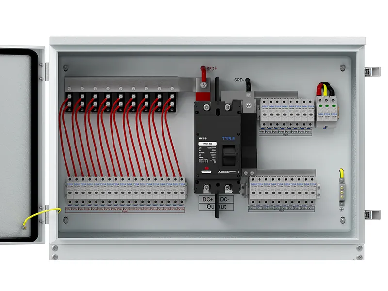
Solar combiner boxes for multi-MPPT inverters should preserve the intended separation between independent tracking circuits. Compatible strings may be grouped for one MPPT, but unrelated trackers should not be connected through a common DC bus unless the inverter manufacturer expressly permits that operating arrangement.
The correct design starts with the inverter’s input map, then assigns strings, output groups and protection. Counting cable sockets or choosing a box by total array power is insufficient. For EPC teams and purchasing engineers, the essential document is a circuit schedule showing which strings feed each MPPT and the ratings along every connection path.
MPPT Channels vs Physical String Inputs
An MPPT channel controls the operating point of its assigned PV circuit to seek maximum available power. An inverter can provide several physical string connectors for one tracker, multiple independent trackers, or input groups with specific operating options.
Two connector pairs therefore do not necessarily mean two independent MPPT channels. Likewise, an inverter with four trackers does not automatically permit four combined outputs of any current.
Read the exact model’s technical data and connection instructions. Identify the number of independent channels, inputs per channel, operating-current limits, permissible short-circuit current and any restrictions associated with arc-fault equipment or connectors.
A pass-through protection box can retain separate string circuits without paralleling them. A combining box can reduce several strings to one output group. Both arrangements may serve a multi-MPPT system, but their internal circuits and output-current requirements differ.
PV String Grouping by MPPT
Group strings according to their electrical compatibility and the inverter manufacturer’s requirements. Matched module types and equal series module counts are a common basis. Check orientation, tilt and shading conditions as part of the performance design.
Series-connected module count primarily determines string voltage. Parallel string count primarily affects the current entering a group. A combiner does not independently correct voltage mismatch between strings or turn one shared array bus into several independent tracked sources.
Different roof orientations can be assigned to separate MPPT channels where the design benefits from independent tracking. Some validated designs permit mixed orientations on one tracker, so identical orientation should not be presented as a universal rule. The decision requires appropriate modeling and manufacturer acceptance.
Prepare a schedule linking each string identifier to its modules, roof area, combiner group and inverter MPPT. That schedule makes routing changes visible and helps prevent installation teams from combining circuits simply because they share an enclosure.
MPPT, Short-Circuit and Connector Current Limits
MPPT Operating-Current Limits
The sum of parallel strings’ operating currents must be assessed against the MPPT’s permitted input conditions. Use the manufacturer’s array-sizing rules, including applicable allowances for module behavior and bifacial contribution.
A manufacturer may permit some current-related clipping within specified array-sizing limits. That does not mean short-circuit or connector ratings can be exceeded. Keep operating-current suitability distinct from absolute equipment limits.
Permissible Short-Circuit Current
Add the relevant string short-circuit currents for each combined group and apply the project and equipment calculation requirements. Compare the result with the inverter’s permissible short-circuit current for that MPPT or input arrangement.
The inverter may not draw all available operating current, but fault exposure and input suitability still require verification. Do not use expected power clipping as an argument for ignoring the short-circuit limit.
Connector and Cable Ratings
An MPPT rated for 40 A may use two physical inputs with lower individual limits. Sending the full combined current through one connector can be unacceptable even if the tracker total appears sufficient.
Check the combiner output terminals, disconnect, cables and inverter connection as one path. Do not split one combined output across multiple inverter sockets using adapters unless the manufacturer approves that exact configuration and its current sharing.
Independent Combiner Output Groups
For normal independent-tracker operation, strings assigned to MPPT A should feed their defined output pair, and strings assigned to MPPT B should feed theirs. The combiner arrangement must preserve the required circuit separation on the DC conductors.
Separate groups can share an enclosure and a protective bonding arrangement. Shared protective earth is different from joining their DC positive or negative circuits. The correct DC topology must follow the inverter and protection-device instructions.
Review fuse positions, busbars, output switching and SPD connections for each group. One enclosure-level current rating does not tell the reviewer how much current each branch, bus or output can carry.
Input/output notation is also ambiguous. “Four inputs, two outputs” could mean two strings paralleled into each output, four pass-through strings with another termination convention, or a different internal arrangement. Obtain the drawing before accepting the designation.
Some inverters explicitly support parallel operation of selected inputs or trackers. Use that exception only with the approved wiring, configuration and limits. It is not a general justification for bridging independent MPPT circuits on other models.
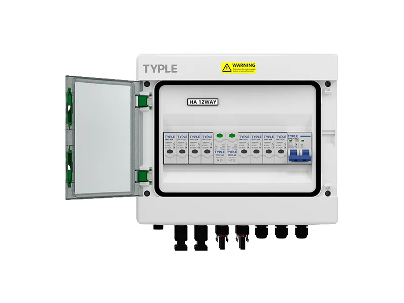
Two-MPPT Combiner Configuration Example
Assume four matched strings, with two assigned to an east-facing roof and two to a west-facing roof. Each string has illustrative operating current of 12 A and STC short-circuit current of 13 A.
The proposed arrangement uses two independent combiner groups: east strings to MPPT A and west strings to MPPT B. Each group has an operating-current sum of 24 A and an STC short-circuit-current sum of 26 A before required design allowances.
| Check | Hypothetical equipment limit | Preliminary finding |
|---|---|---|
| Operating current per MPPT | 30 A | The 24 A sum is below the stated limit |
| Short-circuit current per MPPT | 40 A | The 26 A STC sum still needs required adjustments |
| Current through one connector pair | 16 A | A 24 A combined output cannot be approved through that pair |
| MPPT independence | Two separately tracked circuits | Preserve east and west groups separately |
This design fails the single-connector check even though the preliminary tracker totals appear acceptable. Possible alternatives include retaining separate string inputs through a protection enclosure or using another manufacturer-approved connection arrangement. A splitter is not an automatic solution.
The example also leaves voltage, fusing, temperature, conductor sizing and array-power constraints unresolved. Its numbers illustrate the review process and are not ratings of a real inverter or combiner.
Protection and Cable Sizing for Each MPPT Group
Calculate maximum cold-condition Voc for every string configuration. Verify inverter maximum voltage, MPPT operating range and other relevant voltage conditions, including reduced operating voltage at high module temperature.
Assess string overcurrent protection within each actual parallel group. Strings elsewhere in the enclosure do not automatically contribute to that group’s reverse-current exposure when the DC groups remain separate.
Specify switching and surge protection for the circuits they serve. Where a common operating handle disconnects multiple groups, confirm the device’s documented arrangement and ratings; do not infer safe isolation from handle count alone.
Output conductors must suit the calculated current, terminal temperature limits, installation method and voltage-drop target. Keep labels consistent at string entries, protection devices, outputs and inverter inputs so future maintenance preserves the original MPPT assignments.
Circuit Documentation and Commissioning Checks
Provide suppliers with the exact inverter model, input assignment, module data, strings per group, maximum voltage and current calculations. Request an internal schematic and a bill of materials tied to those groups.
Before energization, qualified personnel should verify polarity, circuit assignment, protective bonding and the tests required by the approved commissioning procedure. Any insulation testing must follow equipment instructions, including handling requirements for connected SPDs and electronics.
A box that contains the requested number of devices can still be wired incorrectly. Acceptance should establish that the fitted arrangement matches the approved circuit map, not merely that components are present.
Conclusion
A suitable multi-MPPT combiner design preserves intended tracking groups and verifies each current and voltage limit along their paths. Map the inputs first, confirm manufacturer-approved topology, and specify protection by group. This approach prevents a correctly sized enclosure from becoming an incorrectly connected PV system.


