

Solar combiner boxes may use string fuses, DC circuit breakers, surge protective devices, disconnect switches and grounding components to protect and isolate photovoltaic circuits. Some designs also include monitoring, arc-fault detection or rapid-shutdown interfaces.
These devices do not all protect against the same hazard. Fuses and breakers respond to overcurrent, SPDs limit transient overvoltage, disconnects provide isolation, and grounding components create a controlled fault-current path.
A reliable combiner box therefore depends on coordinated protection rather than the presence of a long component list.
String Fuses
String fuses are installed in series with individual PV strings. Their main purpose is to interrupt excessive current that could flow into a faulted string, particularly reverse current contributed by other strings connected in parallel.
A PV fuse should be selected according to:
- Module maximum series fuse rating
- String short-circuit current
- Required design-current multipliers
- Conductor ampacity
- Maximum system voltage
- Available reverse or fault current
- Permitted operating temperature
- Required interrupting rating
PV fuses are designed for the operating characteristics of photovoltaic circuits. A general-purpose fuse with a similar ampere rating should not automatically be considered an equivalent replacement.
One-Pole or Two-Pole Fusing
Whether protection is installed on one conductor or both positive and negative conductors depends on the system grounding configuration and applicable rules.
In floating or ungrounded arrays, protection and disconnection may be required in both current-carrying conductors. Grounded arrays can have different requirements. The arrangement must follow the approved system design rather than a generic wiring diagram.
Fuse Holders
Fuse holders must match the fuse dimensions, voltage, current and thermal conditions. They must also be suitable for safe replacement.
A fuse holder should not be opened under load unless the manufacturer specifically permits that operation. A separate load-break disconnect is normally used to isolate the circuit before service.
DC Circuit Breakers
Some combiner boxes use DC circuit breakers instead of, or in addition to, string fuses.
A breaker can provide overcurrent protection and can usually be reset after operation. Some designs also allow switching or isolation, although the exact function depends on the breaker’s ratings and approvals.
Verify:
- Rated DC voltage
- Rated current
- Number of poles
- Polarity requirements
- Interrupting capacity
- Trip characteristics
- Isolation or switching category
- Operating temperature
- Coordination with conductors and modules
DC circuit breakers require particular attention because direct-current arcs are harder to extinguish than AC arcs. Follow the manufacturer’s wiring diagram, including any required series connection of poles.
A circuit breaker with a high nominal current but insufficient interrupting capacity may not safely clear the available fault current.
DC Disconnect or Isolator Switch
A disconnect switch provides a visible or defined means of separating the combiner output from the downstream circuit. This helps technicians isolate equipment during inspection and maintenance.
However, “disconnect,” “isolator” and “load-break switch” do not always describe identical capabilities.
Before selection, establish whether the device must:
- Carry current continuously
- Make or break normal load current
- Interrupt abnormal or fault current
- Provide a lockable isolation point
- Disconnect one or both polarities
- Support remote operation
- Indicate its open or closed state
An isolation-only device should not be operated under load unless it is rated for that function. Overcurrent interruption is normally provided by fuses or circuit breakers rather than by a basic isolator.
Surge Protective Devices
Surge protective devices limit transient overvoltage caused by lightning activity or switching events. They divert surge current away from sensitive equipment and limit the voltage appearing across protected conductors.
In a PV combiner, SPDs may be connected between:
- Positive and negative
- Positive and earth
- Negative and earth
The exact configuration depends on the PV grounding arrangement and SPD design.
Important selection parameters include:
- Maximum continuous operating voltage
- DC system voltage
- Voltage protection level
- Nominal discharge current
- Maximum discharge or impulse current
- Type or class of SPD
- Short-circuit withstand capability
- Backup protection requirements
- Status indication and remote alarm contacts
An SPD should not be selected only by choosing the next voltage rating above the array’s nominal operating voltage. The maximum cold-weather PV voltage and grounding arrangement must also be considered.
SPD Installation Quality Matters
Long connection conductors add inductance and can increase the residual voltage reaching the protected equipment. SPD conductors should therefore follow the manufacturer’s routing and length recommendations.
Proper grounding is equally important. An SPD cannot divert surge energy effectively if the grounding or bonding path is poorly designed.
SPDs can degrade after repeated surge events. Visual indicators or remote alarm contacts help maintenance teams identify modules that require replacement.
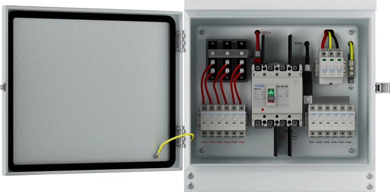
Grounding and Bonding Components
Grounding and bonding terminals connect metallic enclosures, protective conductors and other exposed conductive parts to the site grounding system.
Their purpose is different from that of an SPD. Grounding and bonding create an equipotential and fault-current path, while an SPD responds to transient overvoltage.
A combiner box may include:
- Protective-earth terminal blocks
- Grounding busbars
- Bonding conductors
- Ground lugs
- Enclosure bonding connections
Connections should be sized and installed according to the system design. Paint, corrosion or loose hardware can compromise the continuity of an enclosure bond.
Main Output Protection
In addition to string-level protection, a combiner may include a main output fuse, breaker or switch.
The main output circuit carries the combined current of all connected strings. Its devices and conductors must therefore be rated for the total design current rather than the current of a single string.
Output protection may be needed to protect:
- The outgoing conductor
- Downstream equipment
- The internal busbar arrangement
- Circuits exposed to current from another source
- Parallel combined outputs
Its rating must coordinate with both upstream string protection and downstream inverter or switchgear requirements.
Arc-Fault Detection and Rapid Shutdown
Arc-fault detection and rapid shutdown are sometimes associated with combiner boxes, but they are not standard components in every box.
Arc-fault detection devices monitor for electrical signatures associated with dangerous series or parallel arcs. Rapid-shutdown equipment reduces energized conductor exposure in defined parts of a PV installation when activated.
These functions may instead be integrated into inverters, module-level equipment or separate control units. Whether they are needed depends on the system architecture and local regulations.
They should not be confused with conventional overcurrent protection:
- A fuse does not detect every series arc.
- An SPD does not provide overload protection.
- A disconnect does not automatically provide rapid shutdown.
- Rapid shutdown does not necessarily remove all voltage from individual modules.
Monitoring Devices Are Not Protective Devices
Smart combiner boxes can include current sensors, voltage measurement, internal temperature sensors, fuse-status contacts and communication modules.
These features can alert operators to abnormal conditions, but monitoring alone does not interrupt a dangerous circuit. It must be paired with an appropriate protective or switching device if automatic disconnection is required.
Monitoring is particularly useful for identifying:
- A string producing significantly less current
- A blown string fuse
- An SPD reaching end of life
- Excessive enclosure temperature
- An open disconnect
- Loss of communication with a field combiner
Alarm thresholds should account for irradiance, shading and normal differences between array sections to reduce false alarms.
Protection Device Selection Table
| Device | Primary Function | Does Not Replace |
|---|---|---|
| String fuse | Interrupts excessive string or reverse current | SPD or disconnect |
| DC breaker | Provides overcurrent interruption and, where rated, switching | SPD |
| DC isolator | Creates an isolation point | Overcurrent protection unless specifically combined |
| DC SPD | Limits transient overvoltage | Fuse, breaker or grounding system |
| Grounding busbar | Supports bonding and fault-current paths | SPD or overcurrent device |
| Arc-fault device | Detects defined arcing conditions | General overcurrent and surge protection |
| Monitoring module | Measures conditions and reports alarms | Physical circuit protection |
How to Coordinate the Protection System
Protection devices should be selected as a system:
- Calculate the maximum PV voltage under minimum-temperature conditions.
- Determine the design current for each string.
- Calculate the total combined output current.
- Evaluate reverse current from parallel strings.
- Check module and conductor protection limits.
- Select correctly rated fuses or breakers.
- Determine the required isolation function.
- Select SPDs for the voltage and grounding arrangement.
- Verify grounding and bonding continuity.
- Confirm coordination with the inverter and downstream equipment.
The enclosure’s temperature rating must also be considered. Devices installed close together can produce heat, while direct sunlight may raise the internal temperature above the surrounding ambient temperature.
Conclusion
The principal protection devices used in solar combiner boxes are string fuses or DC breakers, surge protective devices, disconnect switches and grounding components. Larger or more advanced boxes may also include main output protection, arc-fault functions and monitoring.
Each device addresses a different risk. Effective protection depends on correct voltage, current, interruption, environmental and coordination ratings—not simply on including every available component. Final specifications should be checked against the module data, inverter manual, single-line diagram and electrical standards applicable to the installation.


