
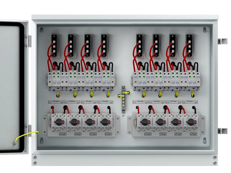
Solar combiner box fuse sizing starts with the current and voltage of each PV string, not the total array wattage. A suitable string fuse must carry the expected operating current, interrupt the available fault current within its specified operating range, and remain within the protection limits of the module, conductors and fuse holder. Its DC voltage rating must also cover the highest calculated string voltage.
These checks create a permitted selection range. Choosing a larger fuse to stop repeated failures can leave the circuit inadequately protected. Choosing the smallest available rating can cause unnecessary interruptions, especially inside a hot enclosure. For EPC contractors and equipment buyers, the useful output is a documented fuse selection supported by module data and the approved system design.
String Fuse Functions and Reverse-Current Protection
Modules connected in series form a string. When compatible strings are connected in parallel inside a combiner box, their currents add at the output. A faulted string can receive reverse current from the other parallel strings, even though its own short-circuit current is relatively limited.
String fuses address this exposure. They do not increase output, regulate voltage or replace surge protection. An output fuse or breaker also does not necessarily protect each individual string against current coming from neighboring strings.
Whether string overcurrent protection is required depends on the available backfeed, module limits, conductor ratings, inverter behavior and applicable installation rules. The number of parallel strings matters, but a universal rule such as “every two-string array needs fuses” is not a sufficient design method.
For initial reasoning, the contribution from the remaining strings increases with their number. Final calculations must use the required design-current factors and include any other source capable of feeding the fault. Evaluate each electrically independent combiner group separately.
Module and Circuit Data for Fuse Selection
Collect the following information before specifying solar combiner box fuses:
| Input | Selection purpose |
|---|---|
| Module short-circuit current, Isc | Establishes the current calculation basis |
| Maximum series fuse rating | Sets the module manufacturer’s permitted protection limit |
| Module open-circuit voltage, Voc | Supports maximum string-voltage calculation |
| Voc temperature coefficient and minimum design temperature | Account for increased voltage in cold conditions |
| Modules in series and strings in parallel | Define voltage and backfeed exposure |
| Corrected conductor ampacity | Establishes conductor protection constraints |
| Fuse-link and holder data | Confirm compatibility, temperature behavior and fault rating |
Bifacial modules require particular attention. Use the module manufacturer’s instructions and the applicable design method to account for rear-side contribution where relevant. The front-side STC current alone may not describe the required design current.
Also distinguish Isc from operating current at maximum power, Imp. They describe different conditions and should not be substituted simply because one value produces a more convenient fuse rating.
Minimum and Maximum Fuse Current Ratings
Minimum Fuse Rating
The lower boundary comes from the required design current, continuous-loading provisions and the selected fuse manufacturer’s application guidance. Apply the installation standard adopted for the project, using the relevant edition and equipment conditions.
A factor of approximately 1.56 times module Isc appears in established NEC-based application guidance because two 125% factors can apply. It is not a universal international formula. Other design methods, equipment ratings and installation provisions can change the calculation.
Do not combine unrelated factors from different standards or apply the same margin twice. Record what each factor covers so the engineering reviewer can distinguish irradiance allowance, continuous loading and product derating.
Module and Conductor Protection Limits
The selected rating must not exceed the module manufacturer’s maximum series fuse rating. That value is a protection ceiling, not a recommended fuse size for every installation.
Check conductor protection under the adopted rules, together with holder, terminal and assembly limits. A fuse holder marked for a particular current does not prove that the complete enclosure can carry that current continuously at its operating temperature.
If the calculated lower boundary exceeds an applicable upper boundary, there is no acceptable selection within that configuration. Revisit the conductors, equipment, module choice or array grouping instead of rounding up and ignoring the conflict.
Temperature Derating
Ambient temperature around the fuse can be higher than outdoor air temperature because of solar exposure and losses inside the enclosure. Closely mounted holders and neighboring devices can also affect heat removal.
Use the fuse manufacturer’s derating information and the assembly’s thermal assessment. Avoid transferring one product’s correction factor to another fuse family. Increasing the current rating is acceptable only if the resulting choice still satisfies every protection limit.

DC Voltage Rating and Interrupting Capacity
A PV fuse must have a DC voltage rating suitable for the maximum calculated voltage at its location. Nominal inverter voltage and module operating voltage are insufficient selection inputs.
For a preliminary calculation with a linear percentage coefficient:
Maximum string Voc ≈ modules in series × module Voc at STC × [1 + absolute Voc temperature coefficient × (25°C − minimum design temperature)].
Use the coefficient as a decimal per degree, not an unconverted percentage. Follow the module manufacturer’s calculation instructions and include additional allowances required by the adopted method.
Interrupting capacity is a separate requirement: the fuse must safely clear the prospective DC fault current at the relevant voltage. A high voltage rating does not imply adequate interrupting capacity.
PV-specific gPV fuse-links are designed for photovoltaic protection characteristics. Confirm the exact certification, operating range and manufacturer instructions. An ordinary AC cartridge fuse or automotive fuse is not an equivalent replacement merely because its ampere rating matches.
Solar Combiner Box Fuse Sizing Example
Consider a hypothetical string with module Isc of 13 A and a maximum series fuse rating of 25 A. Assume the project’s approved method requires a preliminary multiplier of 1.56 and that the product series offers a 25 A fuse.
The preliminary minimum becomes 13 × 1.56 = 20.28 A. The 25 A candidate meets that initial current requirement and the module’s 25 A ceiling. It is not yet an approved selection.
Now assume the approved product-selection method requires an additional, non-overlapping temperature correction of 0.80 against that preliminary selection requirement. The corrected selection value for the 25 A candidate would be 20 A. That is below the preliminary 20.28 A requirement. A 30 A substitution would exceed the module ceiling, so it cannot solve the conflict.
The designer must change the thermal conditions, select an appropriately documented alternative, or revise the circuit design. Voltage, fault interruption, conductor protection and holder compatibility remain independent checks. The example illustrates a decision process; its assumed factors are not specifications for a real project. Do not combine a continuous-loading allowance with a correction that already includes the same allowance.
Fuse and Holder Compatibility Checks
The bill of materials should identify the fuse manufacturer, series, current and DC voltage rating, utilization category, physical format and compatible holder. Where the design relies on a thermal correction, retain the supporting document.
Physical fit is only one acceptance criterion. A replacement with identical dimensions may have different power dissipation, time-current behavior or DC interruption performance. Check these characteristics before approving alternative suppliers.
For inspection, compare fitted fuse markings against the approved schedule. Investigate repeated operation before replacing a fuse: possible causes include a real fault, damaged contacts, incorrect loading or excessive temperature. A fuse holder should not be assumed suitable for opening a loaded DC circuit unless expressly rated for that duty.
Frequently Asked Questions
Can every string use the same fuse rating?
Matched strings within the same design conditions often can. Mixed module currents, separate sub-arrays or different thermal conditions require individual verification rather than one rating across the entire site.
Does a blown fuse always indicate a defective module?
No. Backfeed faults, wiring damage, holder problems and an unsuitable rating can also be responsible. Fuse operation identifies a protection event, not its cause.
Can the SPD backup fuse use the string-fuse rating?
Do not assume so. SPD backup protection follows the SPD manufacturer’s specified coordination requirements and concerns a different circuit function.
Conclusion
Correct solar combiner box fuse sizing produces a defensible range rather than a single shortcut number. Establish the required current, apply product-specific temperature checks, respect module and conductor limits, and verify DC voltage, fault interruption and holder compatibility. When these conditions conflict, revise the design rather than increasing the fuse rating without justification.


