
Complete connection schemes for TYPLE TPU7-40PV DC surge protective devices in photovoltaic systems
Technical Review:
TYPLE Engineering Team
Last Updated:
May 26, 2026
Introduction
The TYPLE TPU7-40PV is a Type II DC surge protective device (SPD) designed for photovoltaic systems from 500 V to 1500 V DC. Built on the IEC 61643-31 standard with a nominal discharge current In of 20 kA and maximum discharge current Imax of 40 kA (both 8/20 µs waveform), the TPU7-40PV is available in 2-pole (36 mm width) and 3-pole (54 mm width) configurations to suit grounded and ungrounded PV installations alike. This guide presents five proven wiring schemes – from basic 2P connection to full PV combiner box integration – to
help solar engineers, system integrators, and EPC contractors select the correct DC SPD installation topology for residential, commercial, and utility-scale projects.
Scheme A · 2P DC SPD Basic Wiring

Overview
Scheme A is the simplest 2-pole DC SPD wiring configuration, using a 1+1 topology in which two metal oxide varistors (MOVs) are connected directly between the DC+ / DC− conductors and the PE earth busbar. The TPU7-40PV 2P module mounts on a standard 35 mm DIN rail and occupies only 36 mm of cabinet width, making it ideal for compact residential solar inverters, small commercial rooftop systems, and battery storage installations operating at DC 500 V to 1000 V.
Connection details
Before powering on the system, verify the wire entry sequence: the DC+ conductor (red) connects to the top-left terminal of the SPD module (MOV 1 input), while the DC− conductor (black) connects to the top-right terminal (MOV 2 input). The PE (protective earth) wire exits from the bottom-center terminal of the 2P module and must be routed directly to the cabinet’s main ground busbar – avoid loops, sharp bends, or shared earthing paths with other equipment, as these add parasitic inductance that degrades surge protection performance. Wire sizing follows IEC 60364 recommendations. Use a minimum cross-section of 4 mm² for DC+ and DC− conductors, and at least 6 mm² for the PE earth wire – or matching the cross-section of the main DC supply conductors, whichever is larger. All conductors should be finely-stranded copper to ensure flexibility during installation and to minimize contact impedance at the SPD terminals.The most critical installation parameter is total wiring length. The sum of the lead-in wire from the main DC bus to the SPD plus the earthing wire from the SPD to the ground busbar must not exceed0.5 meters. This requirement exists because the residual voltage (Up) seen by the protected equipment depends not only on the SPD’s intrinsic clamping voltage, but also on the inductive voltage drop along these wires during a fast-rising surge event (8/20 µs waveform). Every additional 10 cm of cable adds approximately 100 V to the let-through voltage at 10 kA discharge current – significantly reducing the effective protection level.
Key technical points
- SPD module:
TPU7-40PV (2-pole) - Internal topology:
1+1 (two MOVs to PE) - Rated DC voltage Ue:
500 / 600 / 1000 V DC - Protection level Up:
2.2 kV (at 500 V) / 3.6 kV (at 1000 V) - Nominal discharge current In:
20 kA (8/20 µs) - Maximum discharge current Imax:
40 kA (8/20 µs) - Recommended DC cable:
≥ 4 mm² copper, finely-stranded - Recommended PE cable:
≥ 6 mm² copper, finely-stranded - Maximum total wiring length:
0.5 m - Earthing resistance target:
≤ 10 Ω
When to use this scheme
Choose Scheme A when the budget is constrained, the PV system is small (typically under 5 kW), and the installation has a verified low-impedance ground connection with earthing resistance below 10 Ω. This scheme is appropriate for residential single-string inverters, small off-grid cabins, and educational or demonstration projects. For grid-connected systems above 5 kW, commercial rooftops, and any project with stricter safety and documentation requirements, use Scheme B with backup fuse protection instead.
Scheme B · 2P DC SPD with Backup Fuse (Recommended)
Overview
The 3-pole Y-configuration combines two MOVs with a central gas discharge tube (GDT) in a star (Y) topology. The DC+ and DC− conductors each connect through a dedicated MOV to a common neutral node, which then connects through the GDT to the PE earth terminal. This dual-stage design blocks continuous DC leakage current to under 1 µA – orders of magnitude lower than a conventional 2P SPD – making it uniquely suited for ungrounded (IT-type) and floating PV systems operating up to 1500 V DC, the dominant architecture in modern utility-scale solar plants.
Connection details
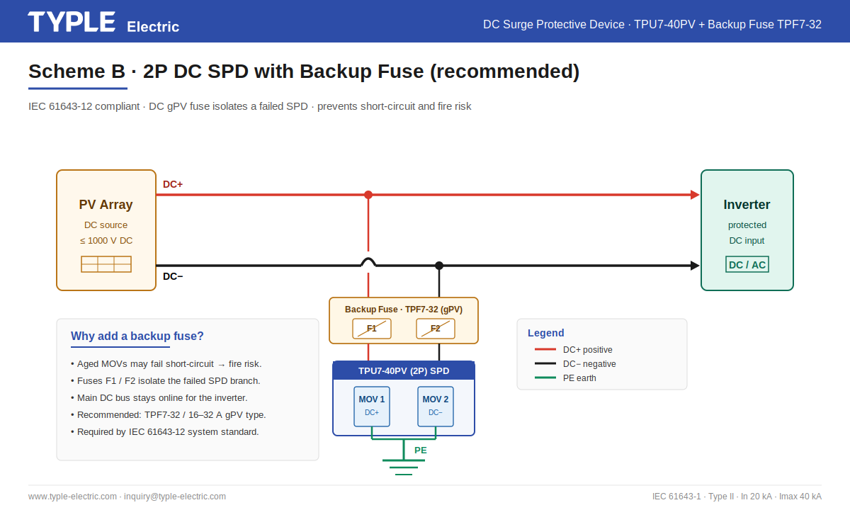
In this scheme, two DC fuses (designated F1 and F2 on the diagram) are installed between the main DC bus and the SPD input terminals. The DC+ conductor passes through fuse F1 before reaching the SPD MOV 1 terminal; the DC− conductor passes through fuse F2 before reaching the MOV 2 terminal. The PE earth wire exits from the SPD bottom center as in Scheme A. All wiring length constraints (≤ 0.5 m total) and cable cross-section requirements (DC ≥ 4 mm², PE ≥ 6 mm²) remain identical to Scheme A. Fuse selection is critical. Use DC gPV-class fuses only – standard AC fuses cannot reliably interrupt DC arc faults and will fail catastrophically in a DC short-circuit. The TYPLE TPF7-32 series is rated 1–32 A at DC 1000 V, with 33 kA breaking capacity and full IEC 60269-6 compliance. For most TPU7-40PV installations, a 16 A or 20 A gPV fuse provides optimal coordination – large enough to withstand surge currents without nuisance tripping, small enough to clear a failed SPD short circuit within milliseconds.
Why a backup fuse is essential
MOVs are the core energy-dissipation element inside any SPD, but they are consumable: each surge event causes microscopic degradation, and the cumulative aging eventually leads to one of two failure modes. The first is gradual leakage current increase, which the TPU7-40PV signals through its status window changing from green to red – a clear visual prompt for scheduled replacement. The second, more dangerous failure mode is abrupt short-circuit failure, where the MOV ceramic disc punctures and creates a low-resistance path between the DC conductor and PE. Without a backup fuse, a short-circuited MOV creates a permanent ground fault on the PV system: continuous DC current flows from the array through the failed SPD to earth, potentially exceeding the rated fault current of the equipment and creating sustained arcing inside the cabinet. This is one of the most common causes of solar combiner box fires worldwide. The backup fuse interrupts this fault current within milliseconds, isolating only the SPD branch while the rest of the system continues to operate normally.
Key technical points
- SPD module:
TPU7-40PV (2-pole) - Backup fuse:
TYPLE TPF7-32, 16–32 A, DC gPV class - Fuse breaking capacity:
33 kA at DC 1000 V - Fuse standard:
IEC 60269-6 - SPD standard:
IEC 61643-31 - System compliance:
IEC 61643-12 - Mounting:
35 mm DIN rail, side-by-side with SPD - Replacement strategy:
Replace fuse + SPD module together
When to use this scheme
Scheme B is recommended for all grid-connected PV installations above 5 kW , including residential rooftops, commercial buildings, and small utility-scale plants. It is also recommended for installations in higher lightning-exposure categories and for projects where the supporting component certificates need to be documented for the authority having jurisdiction. The marginal cost of adding two TPF7-32 fuses is recovered many times over through extended SPD service life and elimination of fire risk
Scheme C · 3P DC SPD Y-Configuration
Overview
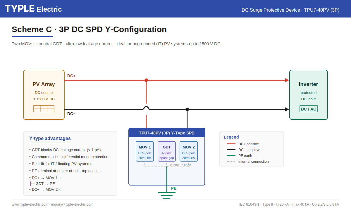
The 3-pole Y-configuration combines two MOVs with a central gas discharge tube (GDT) in a star (Y) topology. The DC+ and DC− conductors each connect through a dedicated MOV to a common neutral node, which then connects through the GDT to the PE earth terminal. This dual-stage design blocks continuous DC leakage current to under 1 µA – orders of magnitude lower than a conventional 2P SPD – making it uniquely suited for ungrounded (IT-type) and floating PV systems operating up to 1500 V DC, the dominant architecture in modern utility-scale solar plants.
Connection details
The TPU7-40PV 3P module is 54 mm wide and occupies three positions on a 35 mm DIN rail. Unlike the 2P version, the PE earth terminal is located at the top center of the module (between the DC+ and DC− input terminals), not at the bottom. The DC+ conductor enters MOV 1 at the top-left; the DC− conductor enters MOV 2 at the top-right; and the PE earth wire enters the GDT (N pole) at the top-center position. This top-entry PE arrangement simplifies wiring in shallow combiner boxes where vertical clearance below the DIN rail is limited. The Y-type topology delivers two distinct protection modes simultaneously.
Common-mode protection
(DC+ to PE, DC− to PE) is provided by each MOV in series with the central GDT, suppressing surges induced by lightning strikes on the building grounding system.
Differential-mode protection
(DC+ to DC−) is provided by the two MOVs in series, suppressing surges induced between the PV string conductors themselves. This dual capability eliminates the need for a separate differential-mode SPD in most applications.
Why GDT matters in ungrounded PV systems
Modern utility-scale PV plants typically operate at1500 V DC with ungrounded (floating)array architectures, where neither DC+ nor DC− is bonded to earth. This design improves system efficiency, simplifies cabling, and enables longer string lengths – but it also requires SPDs with extremely low leakage current to avoid triggering false alarms on the inverter’s insulation monitoring device (IMD). A conventional 2P SPD with MOVs directly connected to PE allows a small continuous DC current to flow to earth (typically several µA), which an IMD interprets as an insulation fault. The GDT in the Y-type 3P SPD solves this by acting as an open circuit during normal operation – its very high impedance blocks DC current – while still igniting within nanoseconds when a surge event exceeds its sparkover voltage, providing full surge protection without compromising the floating system architecture.
Key technical points
- SPD module:
TPU7-40PV (3-pole) - Internal topology:
Y-type (MOV + GDT + MOV) - Rated DC voltage Ue:
up to 1500 V DC - Protection level Up:
5.3 kV (at 1500 V) - Nominal discharge current In:
20 kA (8/20 µs) - Maximum discharge current Imax:
40 kA (8/20 µs) - Leakage current:
< 1 µA - PE terminal position:
Top center - Protection modes:
Common-mode + differential-mode
When to use this scheme
Choose Scheme C for utility-scale PV plants, string inverters operating at 1500 V DC, and any installation using an ungrounded (IT) DC architecture with insulation monitoring. The 3P Y-type SPD is also the preferred choice for high-altitude installations, polar
climate projects, and PV systems with extended cable runs (>50 m between array and combiner box) where induced surge voltages between conductors can exceed the threshold of common-mode-only protection.
Scheme D · DC SPD Installation in a PV Combiner Box
Overview
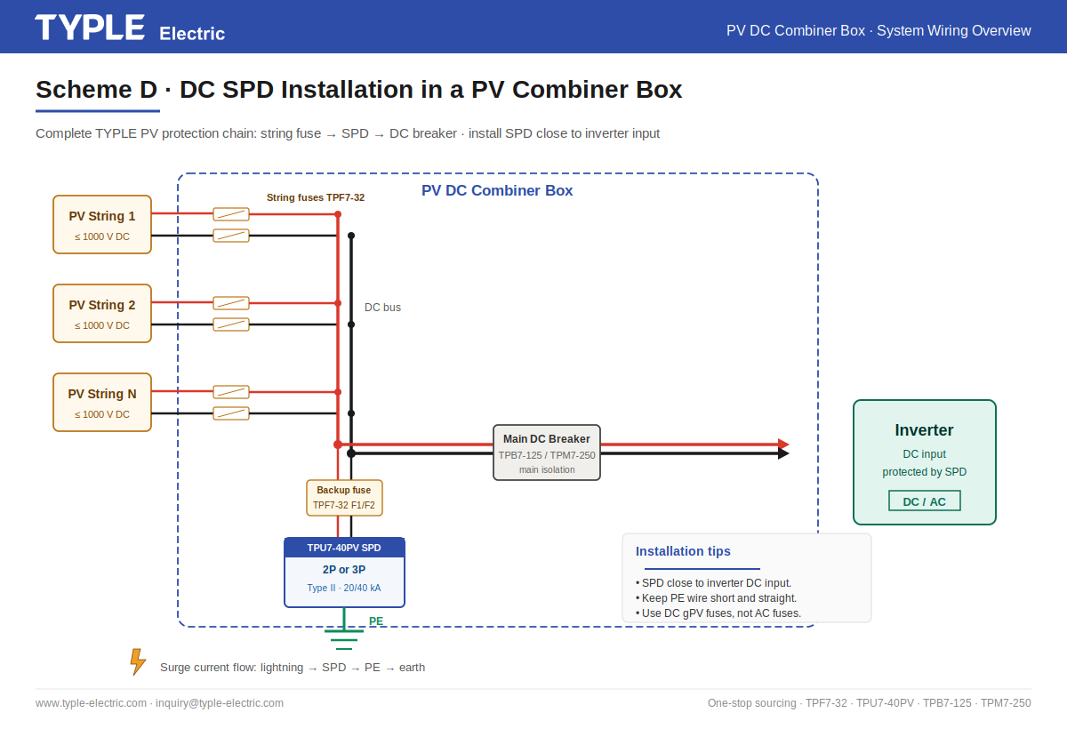
Scheme D illustrates the complete TYPLE protection chain inside a photovoltaic DC combiner box. Each PV string is individually protected against overcurrent by a dedicated string fuse (TPF7-32, 10×38 mm format). Multiple strings are then combined onto a common DC bus, where a centralized DC SPD (TPU7-40PV in 2P or 3P configuration) installed close to the inverter input absorbs lightning and switching surges. Finally, a main DC molded-case circuit breaker (TPB7-125 for systems up to 125 A, or TPM7-250 for 160–250 A applications) provides full isolation for maintenance and emergency shutdown.
Connection details and component coordination
The protection chain operates on three distinct fault types, each handled by a different component.
Overcurrent faults
caused by reverse current from a shaded or damaged string are cleared by the individual string fuses, which use the TPF7-32X model with an integrated visual blown-fuse indicator for fast field diagnostics.
Surge events
caused by direct or induced lightning strikes are absorbed by the TPU7-40PV SPD, which is installed in parallel with the DC bus immediately upstream of the inverter input – the closer to the protected equipment, the lower the let-through voltage.
Short-circuit and overload faults
in the main DC line are interrupted by the main DC breaker (TPB7-125 or TPM7-250), which also serves as the manual disconnect for maintenance. The SPD branch itself is protected by its own dedicated backup fuses (also TPF7-32, typically 16–20 A rating), ensuring that any SPD failure does not propagate to the main DC bus. The PE earth wire from the SPD must connect tothe
same equipotential bonding busbar
used for the combiner box enclosure, PV module frames, and array mounting structure – never to a separate earth electrode, as potential differences between ground points can drive damaging currents through sensitive electronics during a lightning event.
Components used in this scheme
- String fuses:
TPF7-32 / TPF7-32X (1–32 A, 10×38 mm, DC 1000 V gPV) - DC SPD:
TPU7-40PV (2P for ≤ 1000 V, 3P for 1500 V) - SPD backup fuse:
TPF7-32 (16–20 A, gPV class) - Main DC breaker:
TPB7-125 (up to 125 A) or TPM7-250 (160–250 A) - Combiner box enclosure:
TPX7-P series (IP65, IK10, UV-resistant) - PV connectors:
TPPVT MC4-compatible (1000 V or 1500 V variants)
One-stop sourcing advantage
All components shown in Scheme D are manufactured or supplied by TYPLE with matched ratings and verified electrical coordination. The combiner box is engineered to align with IEC 61439, and its protection components are designed to IEC 60947-2, IEC 61643-31, and IEC 60269-6, with component certificates available through TYPLE’s qualified partner suppliers. Sourcing the full protection chain from one supplier reduces compatibility risk, consolidates the supporting documentation, and shortens project delivery compared with multi-vendor sourcing.
When to use this scheme
Scheme D is the standard reference design for EPC contractors, combiner box OEMs, and solar system integrators building multi-string PV projects from 5 kW residential up to multi-megawatt utility plants. The exact component selection within the chain scales with system size: residential projects typically use TPB7-125 main breakers and 2P SPDs, while utility-scale projects use TPM7-250 main breakers and 3P SPDs for 1500 V DC strings.
Scheme E · 2P vs 3P DC SPD – How to Choose
Overview
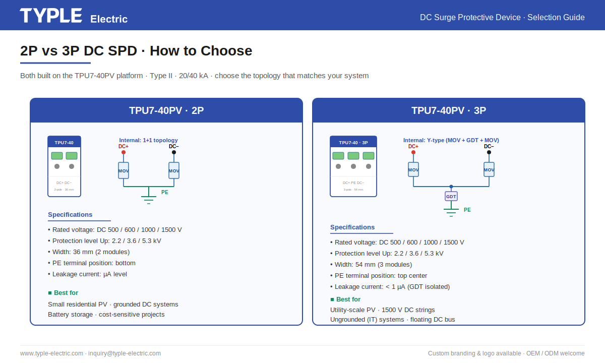
The TPU7-40PV is available in two configurations — 2-pole and 3-pole — built on the same surge protection platform with identical In (20 kA), Imax (40 kA), and IEC 61643-31 Type II classification. The choice between the two depends primarily on three factors:
system voltage grounding architecture, and leakage current tolerance
Side-by-side comparison
| Criterion | TPU7-40PV 2P | TPU7-40PV 3P |
|---|---|---|
| Internal topology | 1+1 (MOV + MOV) | Y-type (MOV + GDT + MOV) |
| Rated DC voltage Ue | 500 / 600 / 1000 V | up to 1500 V |
| Protection level Up | 2.2 / 3.6 kV | 5.3 kV |
| Leakage current | µA level (continuous) | < 1 µA (GDT-blocked) |
| Module width | 36 mm (2 modules) | 54 mm (3 modules) |
| PE terminal position | Bottom | Top center |
| Protection modes | Common-mode | Common-mode + differential-mode |
| Best suited for | Grounded PV, residential, battery storage | Ungrounded (IT) PV, utility-scale, 1500 V systems |
| Typical applications | < 5 kW – 100 kW grounded systems | > 100 kW commercial / utility-scale plants |
Decision logic
Choose the 2P model
when the DC system is reliably grounded (DC+ or DC− bonded to PE), the operating voltage does not exceed 1000 V DC,and project budget is a primary constraint. The 2P version is the most common choice for residential rooftop PV in markets using TN-S or TN-C-S grounding systems, for off-grid solar installations, and for battery storage system DC inputs.
Choose the 3P model
when any of the following conditions apply: the DC system is ungrounded (floating, IT architecture); the operating voltage is 1500 V DC; the inverter uses an insulation monitoring device (IMD) that would be triggered by continuous SPD leakage current; differential-mode protection between DC+ and DC− is required by the project specification; or PE wiring access from the top of the cabinet is preferred for installation ergonomics. The 3P model is the dominant choice for utility-scale PV plants, central inverter applications, and high-end commercial rooftop projects above 100 kW.
Both share the same TYPLE platform
Whichever configuration you select, both 2P and 3P models share the same TPU7-40PV product platform: identical surge ratings (In 20 kA / Imax 40 kA, 8/20 µs), IEC 61643-31 Type II classification, -30 °C to +70 °C operating temperature range, 35 mm DIN rail mounting, and the same visual status window for end-of-life indication. OEM/ODM customization — including custom branding, terminal arrangements, and color options — is available for both versions with low minimum order quantities.


