
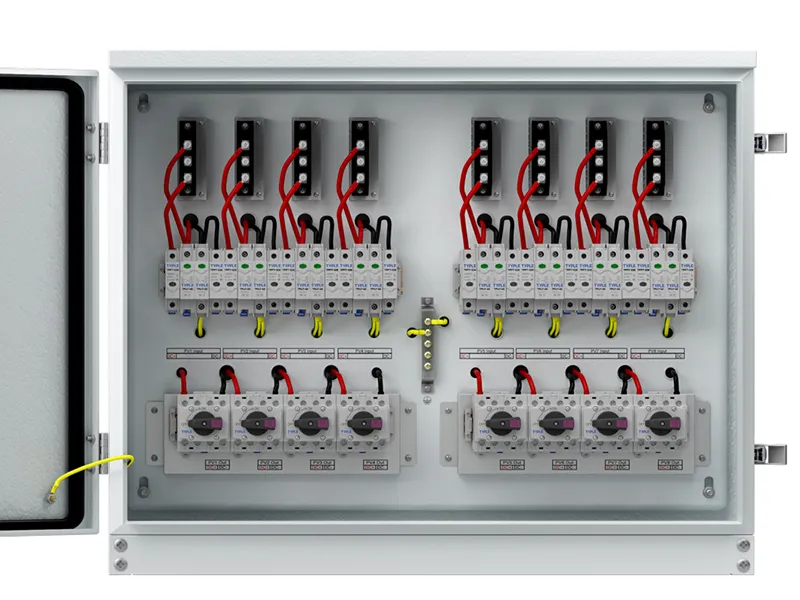
Solar combiner box surge protection uses PV-rated surge protective devices to limit transient overvoltages on the DC circuits. Selecting an SPD requires more than matching a “1000 V” label or choosing the highest discharge-current number. The device must suit the maximum array voltage, protective topology, prospective fault current and equipment being protected.
For project specifiers, the key distinction is between normal voltage tolerance and surge limitation. Ucpv describes the voltage the SPD can withstand continuously, while Up describes its declared voltage protection level during defined tests. Both matter, together with the installation layout and the manufacturer’s coordination requirements.
SPD Functions in Solar Combiner Boxes
Lightning-related electromagnetic effects and other transient events can produce brief overvoltages on PV conductors. An SPD provides a protective path that limits the voltage across the modes it is designed to protect.
In a typical combiner arrangement, the SPD is connected as a parallel protective branch. It is not the series device carrying all array output current, although certain enclosed protection assemblies include pass-through terminals with their own load ratings.
String fuses and circuit breakers perform different functions. They provide specified overcurrent protection and do not replace an SPD. Equally, an SPD does not replace a disconnect, repair an insulation fault or correct excessive steady-state voltage caused by too many modules in series.
A complete surge-protection arrangement can involve equipment at the array, inverter and AC distribution side. One DC device should not be described as protecting the entire installation under every possible lightning condition.
Key PV SPD Ratings
| Parameter | Meaning | Selection question |
|---|---|---|
| Ucpv | Maximum continuous operating voltage for PV use | Can the device tolerate the calculated voltage continuously? |
| Up | Declared voltage protection level | Is the protective performance coordinated with equipment withstand? |
| In | Nominal discharge current under the stated test waveform | What declared repetitive surge-duty capability is provided? |
| Imax | Maximum discharge current under the stated waveform | What maximum tested discharge capability is declared? |
| Iimp | Impulse-current rating associated with Type 1 testing | Is lightning-current duty required and adequately rated? |
| Iscpv or stated PV short-circuit rating | Fault-current capability under specified conditions | Is the protective device suitable for available PV fault current? |
The ratings must be read with their test conditions and protective modes. A total discharge-current value may not be directly comparable with a per-mode value from another product.
Similarly, In and Imax commonly refer to an 8/20 microsecond waveform, while Iimp is associated with a 10/350 microsecond waveform. Equal ampere numbers under different waveforms do not indicate equal duties. Avoid procurement tables that collapse all these values into a single “surge capacity” column.
Ucpv and Maximum PV String Voltage
PV open-circuit voltage rises as cell temperature falls. The selection basis is the maximum calculated voltage at the SPD’s terminals under the project design conditions, not simply the module’s operating voltage or the inverter’s nominal voltage class.
Confirm modules in series, module Voc, the relevant temperature coefficient and minimum design temperature. Use the approved calculation method and any required additional allowances. Also verify the voltage ratings of other components on the same circuit.
An SPD with insufficient Ucpv can be exposed to abnormal continuous electrical stress even without a lightning event. A device with a higher Ucpv may tolerate the normal circuit voltage, but that does not automatically mean better equipment protection.
Increasing the voltage class can alter the declared Up. Check the complete combination rather than selecting the highest voltage available. Product naming can also distinguish nominal generator voltage, allowable STC open-circuit voltage and Ucpv; these values should not be treated as interchangeable.
For a hypothetical design with calculated maximum string voltage of 920 V, a 600 V Ucpv device is unsuitable. A candidate rated above 920 V still requires topology, Up, fault-current and environmental checks before approval.
Up and the Installed Protection Level
Up describes the SPD’s declared protective voltage level under specified test conditions. Equipment impulse withstand describes what the protected insulation can tolerate. Selection should coordinate these characteristics using the applicable protection method.
However, the equipment can experience more voltage than the SPD’s declared Up alone. Connecting conductors introduce additional voltage during rapidly changing surge current. Routing and connection length therefore influence the installed protection level.
Keep connections short and direct in accordance with the manufacturer’s instructions. Coordinate the protective bonding arrangement and avoid routing that creates unnecessary loops. A low Up on a datasheet cannot compensate for an unsuitable physical layout.
For long cable runs between the array and inverter, assess whether protection is needed at more than one location. Distance recommendations are part of a specific installation method, not a reason to assume any one device protects equipment regardless of cable length.
Type 1, Type 2 and Combined PV SPDs
Type 2 SPDs address specified surge-current duties and are widely used in PV installations. Type 1 or combined Type 1+2 devices are selected where the protection design requires lightning-current capability.
The choice depends on the external lightning-protection arrangement, separation distance, possible lightning-current paths, installation configuration and applicable rules. An external lightning-protection system does not automatically produce the same SPD requirement at every location.
Do not select the type solely from array size, roof height or a general description such as “high-risk area.” Those details may inform the assessment, but the final specification should identify the required duty at the installation point.
Use devices suitable for PV DC service. An AC SPD with a similar voltage marking is not a substitute unless the manufacturer explicitly approves the exact application. PV-specific operating and failure conditions require appropriate product evidence.
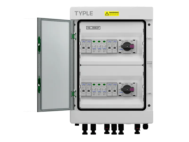
SPD Topology and Backup Protection
Protection Modes and Earthing Arrangements
Confirm the DC earthing arrangement and the required protection between positive, negative and protective earth. Review the SPD’s internal circuit and stated suitability for the installation, including ungrounded or intentionally grounded configurations.
The physical number of modules does not by itself establish the protected modes. Some products use internal configurations that provide several protective paths. Others require different arrangements. Use the manufacturer’s wiring documentation rather than inferring suitability from “two-pole” or “three-pole” terminology alone.
Fault Ratings and Backup Fuse Requirements
An SPD must safely handle its defined failure conditions at the available fault current. Check the PV short-circuit rating and whether external backup protection is required.
Some PV SPDs incorporate a disconnection arrangement that allows operation without a separate backup fuse within stated limits. Others specify external protection. Neither “every SPD needs a 20 A fuse” nor “the internal disconnect always removes the need for a fuse” is a valid universal rule.
The selected backup device must meet the exact type and rating constraints in the manufacturer’s instructions. Do not substitute the string-fuse rating or an unrelated AC protective device without verified coordination.
SPD and Assembly Specification Checklist
Request the exact SPD model, current technical datasheet, protective circuit, installation instructions and relevant product test documentation. Record Ucpv, Up by protective mode, discharge ratings and fault-current limits.
Then check the enclosure layout, connection lengths, bonding terminals, replacement access and status indication. Remote signaling can support maintenance planning, but a contact signal does not establish the remaining surge capability or protect an incorrectly specified circuit.
For multiple independent MPPT groups, verify that the SPD arrangement protects each group without creating unintended DC interconnections. Confirm any integrated inverter protection before deciding whether external devices can be omitted.
Conclusion
Effective solar combiner box surge protection depends on coordinated selection and installation. Start with maximum PV voltage, then verify protective level, surge duty, topology and fault behavior. Complete the review with short connections, suitable bonding and equipment coordination. The finished design matters more than any single impressive SPD rating.


